
How-To
How to Wire a BMS Correctly
Balance leads first, main cables last

Most BMS failures on new builds come from wiring mistakes, not faulty boards. A careful order of work avoids them.
Before you start
- Read the manual for your exact board; wiring varies by model.
- Make sure the cells are already joined in series and parallel and that total voltage is as expected.
- Remove rings and use insulated tools.
Step by step
- Identify the taps. The balance wire harness has one wire at the pack negative, then one after each series group, ending at the pack positive.
- Measure before plugging. With a multimeter, check each tap in turn against the lowest tap. The voltage should step up by one cell voltage (about 3.2 V for LFP, 3.6 V for NMC) at each wire.
- Connect the balance plug. Plug in the harness only after the check passes.
- Connect the main negative. From the pack negative (B-) to the BMS, following the diagram.
- Test outputs. Check voltage on the output terminals before attaching a load.
- Attach the load and charger only after the board shows normal cell readings.
Common mistakes
- Wires in the wrong order, which can destroy the board.
- Thin main cable, causing heat; use copper sized for the current, such as copper busbar for short links.
- Missing fuse on the main positive.
Boards to practise on
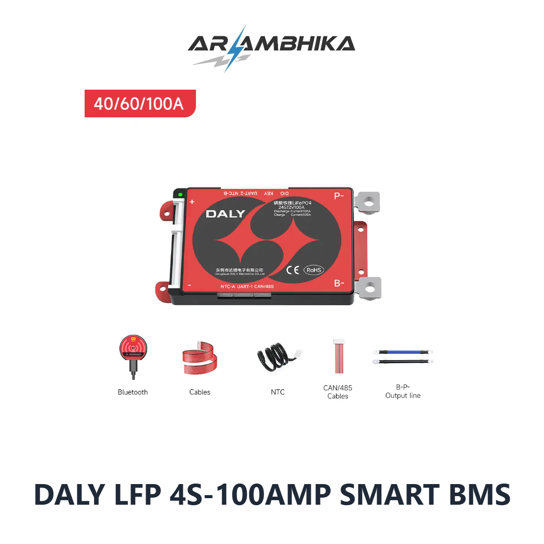
A 4S smart BMS is a simple first board, and the app shows you at once if a cell is wired wrongly.
General guidance only. Check cell, BMS and strip datasheets and the standards that apply to your product before you build or sell a pack.
Products in this guide

BMS and busbar for your build
Live stock and price from our store. Tap a product to add it to your quote.
Loading products…
Frequently asked questions
What do B-, P- and C- mean?
Labels differ by board. Typically B- goes to the pack negative, P- to the load and C- to the charger on a separate-port board. Check your manual.
Can I plug the balance lead in live?
Do the voltage check first and connect only if everything is right. Following the manual order reduces risk.
Do I need a fuse if there is a BMS?
Yes. The BMS does not replace a correctly rated fuse or breaker.